Extrusion & Nibbling
Pressure can force elastomer into a clearance gap. Repeated loading and movement can leave torn or nibbled edges. Check pressure peaks, actual clearance, component deflection, compound hardness and any required backup support.
CUSTOM SOLUTIONS / FAILURE ANALYSIS
A visible failure sign is a useful starting point, not a complete diagnosis. We review the available part, service conditions, gland information, and material evidence to identify the next questions.
We aim to provide an initial response within 12 hours.
01 / REVIEW METHOD
The same visible change can have more than one contributing mechanism. Material, gland condition, sealed media, temperature, pressure, motion, installation, and service history can all matter. A useful review compares the failed part with the actual sealing condition rather than treating one symptom as a final answer.
02 / FAILURE SIGNALS
These sections describe visible clues and the information that helps clarify them. A clue can involve more than one mechanism. These sections do not replace application-specific material or design review.
01 / FAILURE SIGNAL
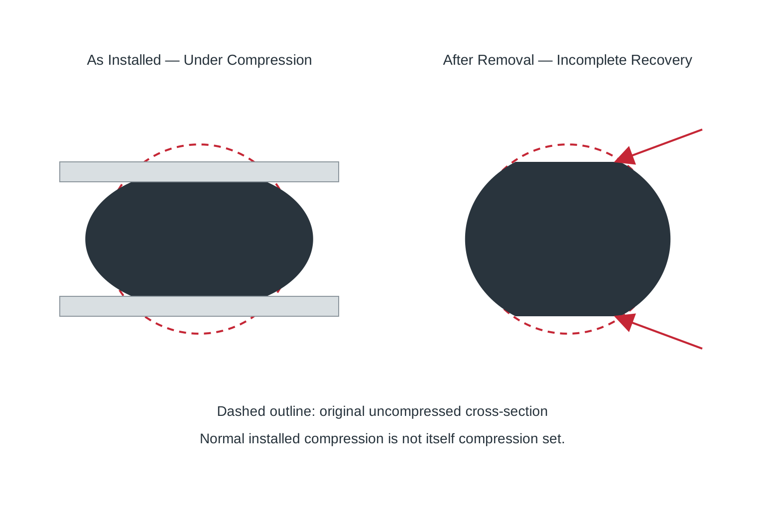
After removal and a period of recovery, a seal may retain flattened contact areas or reduced cross-section height compared with an unused reference. Normal installed compression is not itself compression set.
Compound and cure system, sustained squeeze, temperature, exposure time and media-related changes can affect recovery.
Compare the recovered part with an unused seal and review gland dimensions, squeeze and service history. ASTM D395 measures residual deformation under specified compression and recovery conditions; appearance alone does not quantify compression set.
Retained flats are a clue, not proof of a single cause or inevitable leakage.
02 / FAILURE SIGNAL
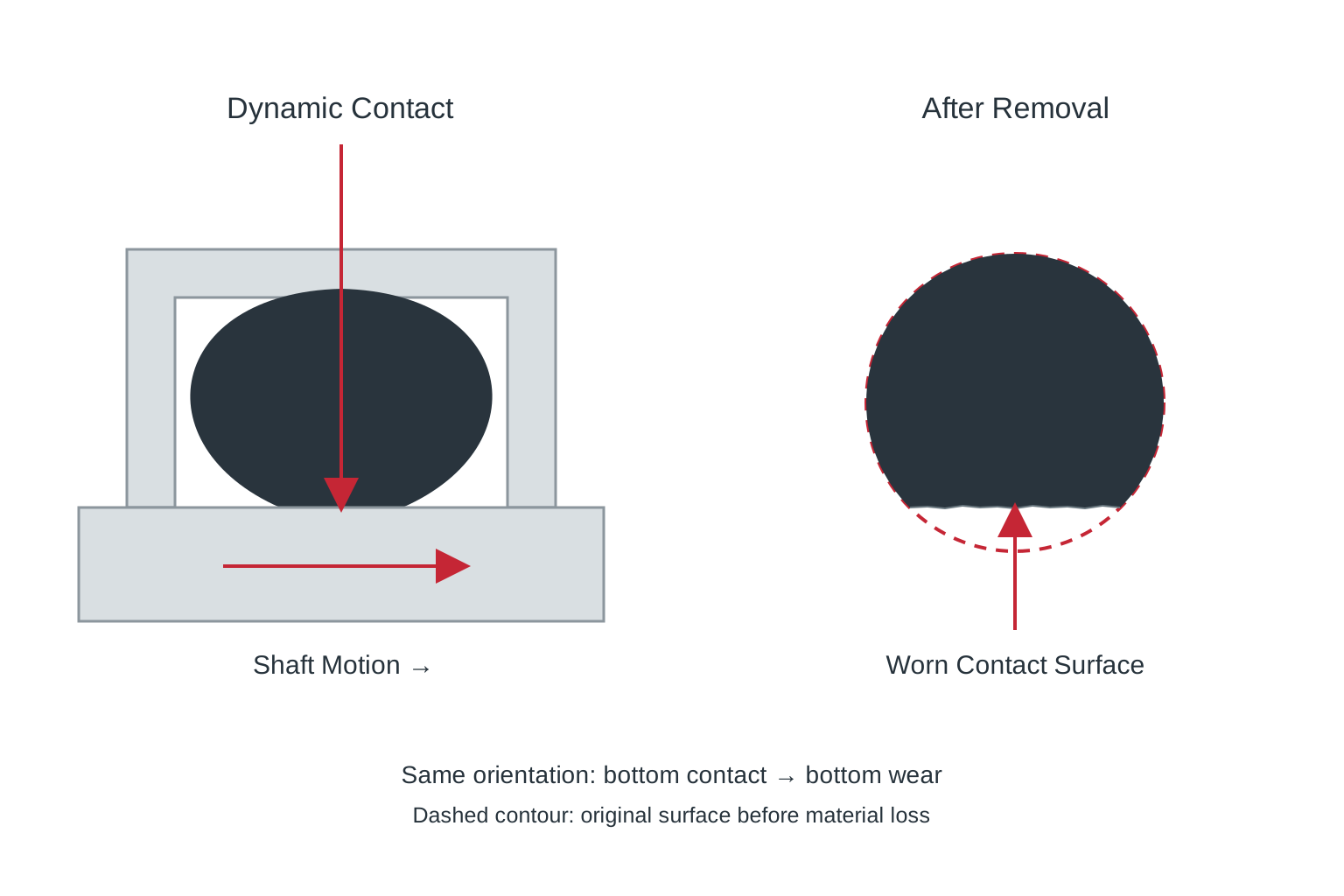
A dynamic contact surface may show local material loss, wear or fine marks along the motion path. The illustrated worn face corresponds to the shaft contact below, rather than deformation on both compression faces.
Mating-surface roughness, inadequate lubrication, particles, misalignment or operating cycles can contribute to wear.
Confirm the moving surface and wear location. Check surface finish, lubrication, contamination, gland alignment and assembly history. Distinguish removed material from retained deformation; more than one mechanism may be present.
A flattened face alone does not establish abrasion.
03 / FAILURE SIGNAL
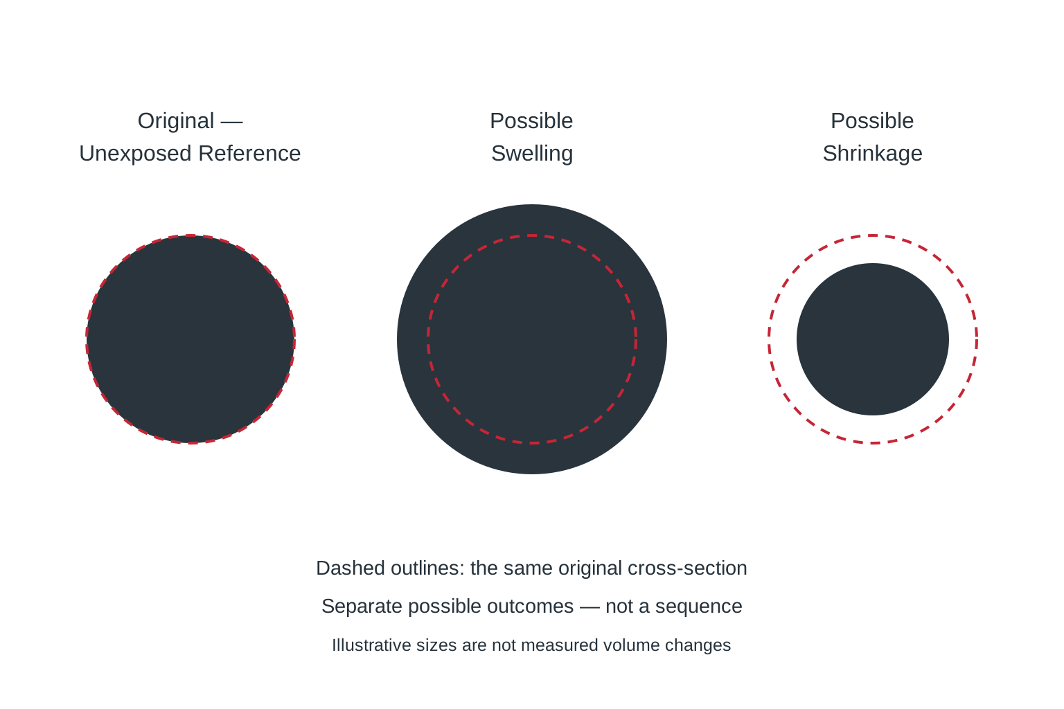
Media exposure may produce swelling, shrinkage or changes in surface condition and elasticity. The three states show separate possible outcomes, not a required sequence; the drawn sizes are not measured volume changes.
Fluid absorption, extraction of soluble ingredients or chemical degradation may contribute. The exact compound, media, concentration, temperature and exposure duration matter.
Compare with an unexposed reference and identify the exact media, additives and cleaning agents. ASTM D471 evaluates changes in rubber properties after controlled liquid exposure; it does not cover every gas exposure or establish field compatibility by itself.
A material family name or compatibility-table rating is not a field-use guarantee.
04 / FAILURE SIGNAL
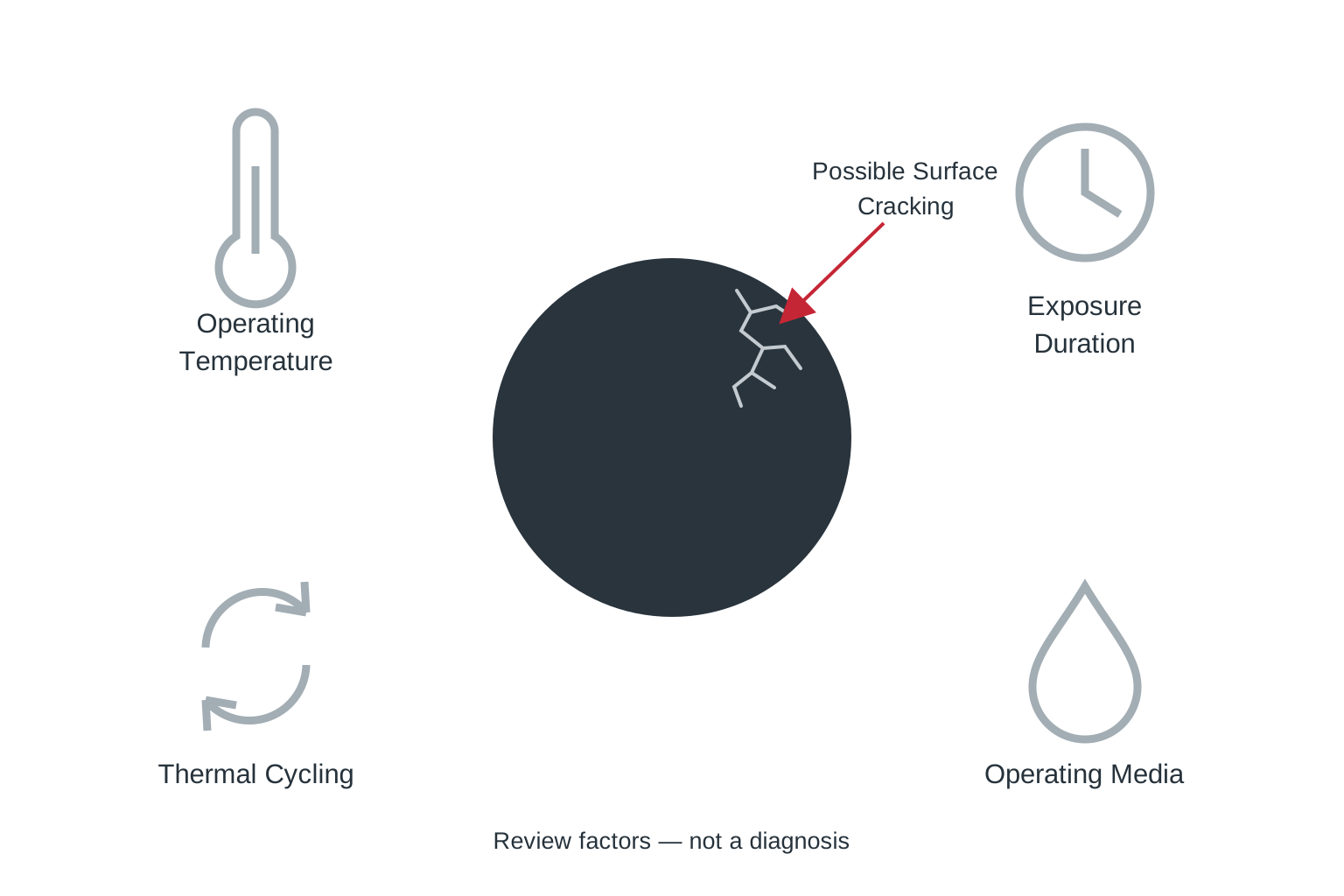
Prolonged heat exposure may change hardness or elastic recovery, and may be accompanied by surface cracking, pitting or retained deformation. Not all heat-related damage appears as cracking.
Operating temperature and duration, thermal cycling, frictional heating, operating media and compound stability can interact.
Review continuous and peak temperatures, time, cycling and media alongside gland and motion conditions. ASTM D573 assesses changes in rubber properties after air-oven aging; it does not reproduce every service environment or prove heat was the root cause.
Cracks alone do not identify excessive temperature; chemical and other mechanisms may overlap.
OTHER REVIEW PATHS
Pressure can force elastomer into a clearance gap. Repeated loading and movement can leave torn or nibbled edges. Check pressure peaks, actual clearance, component deflection, compound hardness and any required backup support.
Sharp edges, exposed threads or assembly tools can scratch or cut a seal during installation. Check lead-in chamfers, thread protection, lubrication, seal position and the assembly path before attributing damage to service conditions.
Gland dimensions, tolerances, squeeze and installation position can affect sealing even when the part looks intact. Review the complete sealing arrangement as well as the seal.
The ASTM methods mentioned above explain controlled material tests, not reports of FLUID testing. Laboratory results do not establish service life or guarantee sealing in a particular application.
07 / TECHNICAL REVIEW INPUTS
The following information can help clarify the next check. It is not required to begin a conversation.
08 / TECHNICAL REVIEW
Tell us the sealing issue and the information available.
We can identify the next information needed for a technical review.
The next discussion may involve the part, service conditions, material evidence, or gland details.
RELATED TECHNICAL PATHS
Need to review a material choice against the application? Explore Material Selection →
Need to discuss seal geometry, gland details or a revised arrangement? Explore Seal Design →
START A TECHNICAL REVIEW
Start with the information available. We can identify the next details needed for a technical review.